Electric Resistance is a measure of the opposition to current flow in an electrical circuit. Resistance is measured in ohms, symbolized by the Greek letter omega (Ω).The resistance of a wire is directly proportional to its length and inversely proportional to its cross section area.
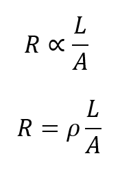
In the above relationship p is a constant of proportionality known as resistivity or specific resistance of the material of the wire.
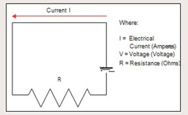
Ohm’s Law V = I x R (Volts = Current x Resistance). The Electric Resistance is measured in Ohm (Ω), the unit of electrical resistance equal to that of a conductor in which a current of one ampere is produced by a potential of one volt across its terminals. Ohm’s law, named after its discoverer the German physicist Georg Ohm, is one of the most important, basic laws of electricity. It defines the relationship between the three fundamental electrical quantities: current, voltage and resistance. When a voltage is applied to a circuit containing only resistive elements, current flows according to ohms Law as shown below.
What is a Low Resistance Measurement?
A low resistance measurement is typically a measurement below 1.000 ohm. At this level it is important to use test equipment that will minimize errors introduced by the test lead resistance and/or contact resistance between the probe and the material being tested. Also, at this level, standing voltages across the item being measured (e.g. thermal emfs at junctions between different metals) may cause errors, which need to be identified.
To allow a measurement to compensate the errors, a four- terminal measurement method is employed with a reversible test current and a suitable Kelvin Bridge meter. Low resistance ohmmeters are designed specifically for these applications.In addition the upper span on a number of these meters will range into kilohms, which covers the lower ranges of a Wheatstone Bridge. The lower range on many low resistance ohmmeters will resolve 0.1 micro-ohms. This level of measurement is required to perform a number of low range resistance tests.
Principles of Electric Resistance Measurement:
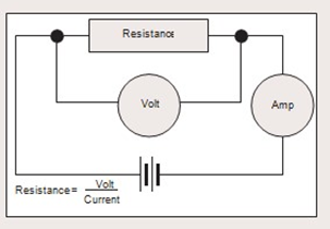
Ammeter Voltmeter method
If we use a battery as our voltage source, a voltmeter to measure the voltage and an ammeter to measure the current in the circuit, we can calculate the resistance with reasonable accuracy. Whilst this method can provide good measurement results, it is not a practical solution to everyday measurement needs. There exists a variety of resistance measuring instruments that will calculate and display the resistance reading without the need for the calculations by the user.
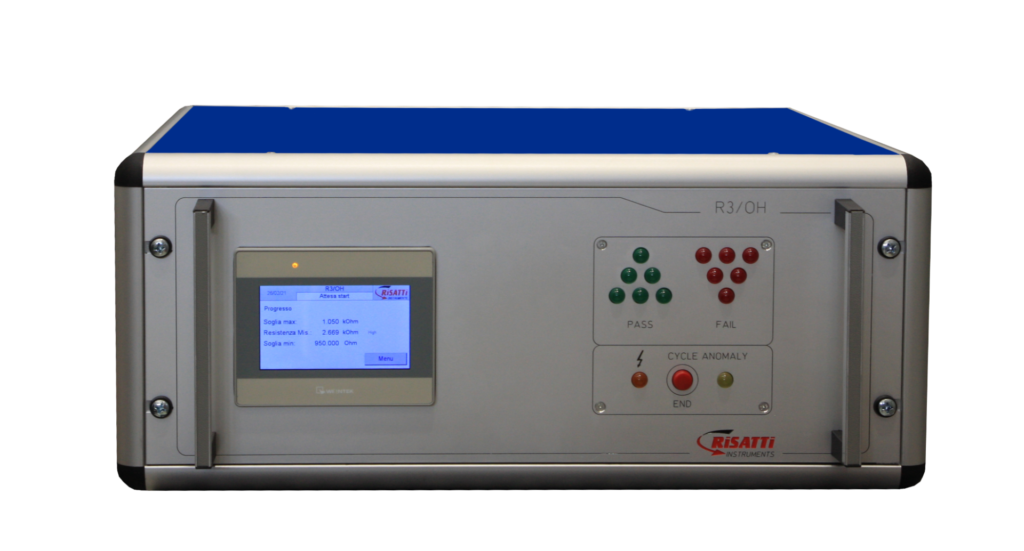
R3/OH – DIGITAL OHMMETER
The attention to design, ease of use and great reliability make these instruments among the best on the market, also favored by a quality/price ratio that is difficult to match.
These tools are designed for industrial environments and are characterized by the possibility of being widely customized.
Two wire and four wire Measurement Method
Two-Wire Measurement Method
Two–wire testing is the simplest method and it is used to make a general assessment of a circuit element, conductor or the routing of a conductor in a circuit. A simple digital multimeter can be used for higher values of resistance. They employ the 2 wire method of measurement and are only suitable for measuring values above 100Ω and where high accuracy is not required.
When measuring the resistance of a component (Rx) a test current is forced through the component and the test meter measures the voltage at its terminals. The meter then calculates and displays the resulting resistance and is known as a two- wire measurement. It should be noted that the meter measures the voltage at its terminals and not across the component. As a result of this, the voltage drop across the connection leads is also included in the resistance calculation. Good quality test leads will have a resistance of approximately 0.02Ω per meter. In addition to the resistance of the leads, the resistance of the lead connection will also be included in the measurement and this can be as high as or even higher in value than the leads themselves.
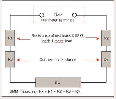
When measuring a large resistance value this additional lead resistance error can be ignored, but as you can see from the chart below, the error becomes significantly higher as the measured value decreases, and totally inappropriate below 10Ω. The two-wire test method is best used for readings above 10.00 ohms up to 1.0 to 10.0 megohms.
| RX | Test lead resistance R1 + R2 | Connection resistance R3 + R4 | Rx measured at DMM terminals = Rx + R1 + R2 + R3 + R4 | Error | Error % |
|---|---|---|---|---|---|
| 1000 Ω | 0.04 Ω | 0.04 Ω | 1000.08 Ω | 0.08 Ω | 0.008 |
| 100 Ω | 0.04 Ω | 0.04 Ω | 100.08 Ω | 0.08 Ω | 0.08 |
| 10 Ω | 0.04 Ω | 0.04 Ω | 10.08 Ω | 0.08 Ω | 0.8 |
| 1 Ω | 0.04 Ω | 0.04 Ω | 1.08 Ω | 0.08 Ω | 8 |
| 100 mΩ | 0.04 Ω | 0.04 Ω | 180 mΩ | 0.08 Ω | 80 |
| 10 mΩ | 0.04 Ω | 0.04 Ω | 90 mΩ | 0.08 Ω | 800 |
| 1 mΩ | 0.04 Ω | 0.04 Ω | 81 mΩ | 0.08 Ω | 8000 |
| 100 µΩ | 0.04 Ω | 0.04 Ω | 80.1 mΩ | 0.08 Ω | 8000 |
Four wire Measurement Method
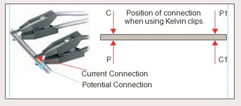
The four wire (Kelvin) method of measurement is preferred for resistance values below 100Ω, and all milliohm meters and microhmmeters use this method. These measurements are made using 4 separate wires. 2 wires carry the current, known as the source or current leads and pass current through the Rx. The other 2 wires known as the sense or potential leads, are used to sense the voltage drop across Rx. While some small current will flow in the sense leads, it is negligible and can be ignored. The volt drop across the ohmmeter’s sense terminals is therefore virtually the same as the volt drop across Rx. This method of measurement will produce accurate and consistent results when measuring resistances below 100Ω.
From a measurement point of view this is the best type of connection with 4 separate wires; 2 current (C and C1) and 2 potential (P and P1). The current wires must always be placed outside the potential although the exact placement is not critical. Potential wires must be connected exactly at the points you want to measure between. The measured value will be between the potential points. Kelvin clips are similar to crocodile (Alligator) clips but with each jaw insulated from the other. The current lead is connected to one jaw and the potential lead to the other. Kelvin clips offer a very practical solution to making a four terminal connection to wires, busbars, plates etc.
Effects of Temperature on Measured Resistance Values
The resistance offered by a conductor to the flow of Electric Current is due to collisions,which the free Electrons encounter with atoms.As temperature of the conductor rise,the amplitude of vibration of the atoms in the lattice increase and probability of their collision with free electrons also increases.Due to more frequently collision between free electron and atoms,resistance of conductor increase.
The change in resistance of metallic conductor with temperature is found to be linear over a considerable range of temperature above and below 0°C. Over such a range the fractional change in resistance per kelvin is known as the temperature coefficient of resistance.

Rt=Resistance at t°C
R0=Resistance at 0°C
There are some substance like silicon and germanium whose resistance decrease with increase in temperature.These substance have negative temperature coefficient.
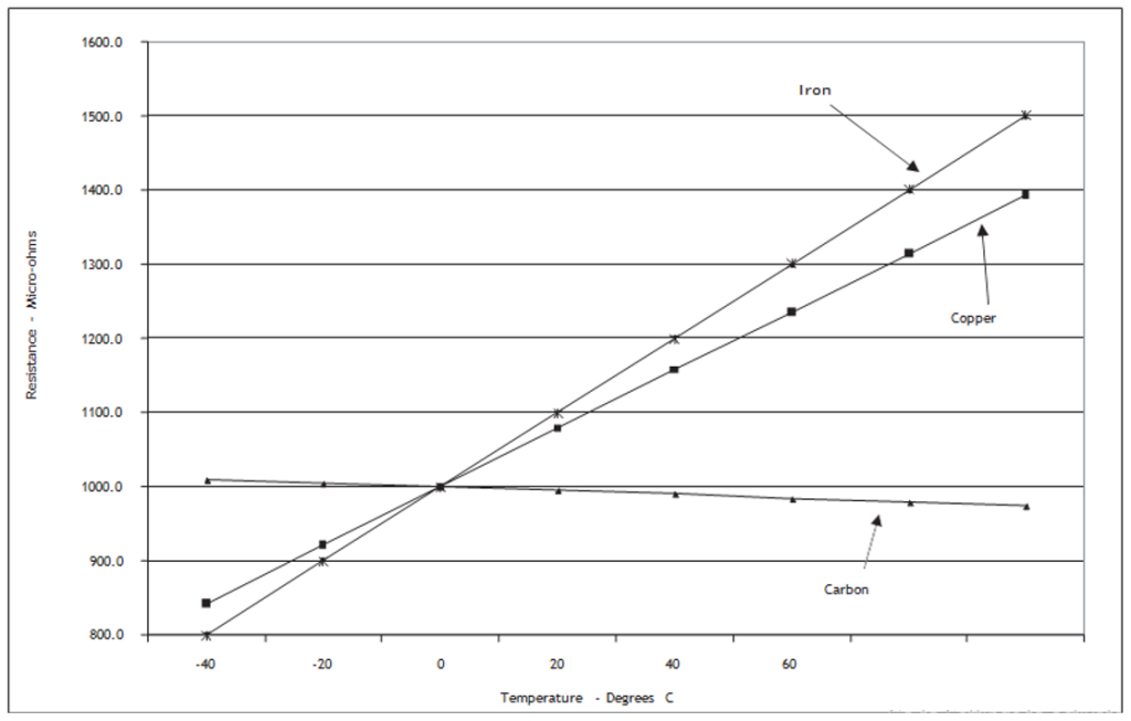
Low resistance measurements rely on the operator conducting the tests within the operating temperature range of the instrument (the operator must be aware of field conditions). When the operator sees out-of-tolerance measurements, one of the first steps is to verify the instrument’s reading with a suitable calibration shunt.The following table shows the temperature coefficients of electric resistance for selected materials.
Temperature Coefficients of Resistance
| Material | Per ºC | Per ºF |
| Aluminum | 0.0038 | 0.0021 |
| Carbon (0-1850 ºC) | -0.00025 | -0.00014 |
| Constantan (0-100 ºC) | negligible | negligible |
| Copper (@ 20 ºC) | 0.00393 | 0.00218 |
| Iron | 0.0050 | 0.0028 |
| Lead | 0.0043 | 0.0024 |
| Manganin (0-100 ºC) | negligible | negligible |
| Mercury | 0.00090 | 0.00050 |
| Platinum | 0.0038 | 0.0021 |
| Silver | 0.0040 | 0.0021 |
| Tungsten | 0.0045 | 0.0025 |
| Zinc | 0.0037 | 0.0021 |
Effect of Humidity on Resistance
The resistance has inverse relationship with the Humidity. As Humidity increase specially during smog season,The insulation resistance decrease. The relative humidity of the test specimen should not affect the resistance reading unless the material is hygroscopic, in which case more moisture will be absorbed into the sample at higher humidities. This will change the measurement conditions and will affect the achieved result. However, most conductors are non-hygroscopic. Therefore, since instruments are typically designed with an operating range of from 0 to 95% RH, providing that moisture is not actually condensing on the instrument then a correct reading will be obtained.
Measurement of Electric Resistance at variable Frequency
The resistance does depend on frequency. The reason is ‘skin effect’. The formula of Skin depth shows that resistivity is directly proportional to frequency. Resistivity is also directly proportional to resistance.

When an alternating current is passed through a conductor only a small portion of the conductor, usually called the skin depth carries the current. The value of skin depth is inversely proportional to frequency. As the frequency is increased, the skin depth decreases. But the value of ac resistance is directly proportional to frequency, or in other words, inversely proportional to skin depth. Thus, at higher frequencies, ac resistance is higher.This is the reason why we multiply the dc resistance by an empirical value 1.2 or 1.3 to calculate its ac equivalent. For a DC source, Resistance doesn’t (cannot because frequency of DC is zero) depend on frequency.
R3/OH – DIGITAL OHMMETER
The attention to design, ease of use and great reliability make these instruments among the best on the market, also favored by a quality/price ratio that is difficult to match.
These tools are designed for industrial environments and are characterized by the possibility of being widely customized.